JRC 650 TO 750 BIG BORE KIT INSTRUCTIONS
DOWNLOAD PDF FILE HERE: TRIUMPH 650 TO 750 BIG BORE
Thank you for choosing our 750 conversion for your Triumph 650. Careful assembly and running in will greatly extend the life of your investment. Assembly is straight forward and well within the scope of the average British cycle enthusiast. There are a few pointers experience has taught us and these we would like to share with you. Please read these directions completely before using this product. If you feel you are unable to install this product properly please contact a qualified British motorcycle dealer for Installation. If you are unable to locate a dealer in your area please call us for a referral.
This unit is manufactured to the highest standard. It is intended for use on street motorcycles and not intended for competition. A factory service manual will be most helpful during this procedure.
It is highly recommended that the oil be changed and Aerco “running in oil” be used with your new cylinder kit. We recommend Aerco running in oil available at better British motorcycle shops. Any 30 weight non-detergent oil can be used if Aerco running in oil can’t be found. We strongly advise against using modern specialty oils for running in. In experience they prevent proper ring seating and can lead to seizure.
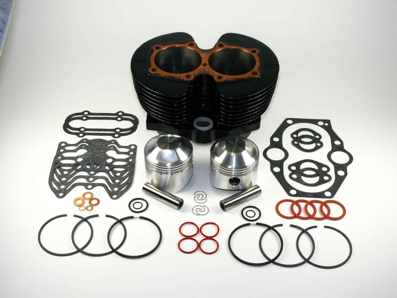
Step 1 Unpack your big bore kit and inspect the contents. There should be the following: 1 Cylinder, 2 pistons with wrist pins, piston ring set x 1, Top end gasket set with head gasket.
Step 2 Thoroughly wash the cylinder bores with soap and water, do not use solvent. Dry bores with air or a lint free towel and let completely air dry. This step is most important and will greatly extend the life of the pistons.
Step 3 Following the procedure outlined in your service manual drain the fuel tank, remove the exhaust system, Fuel tank and carburetors. Have a catch basin handy to capture any fuel that may spill from the carburetors. Warning! Fuel is highly flammable and can be ignited by a dryer pilot light from a long distance. Clean up any spilled fuel immediately and dispose of away from any source of ignition. Store the fuel tank in a well vented area, outdoors is best; in the event you fuel taps should leak.
Step 4 Remove the rocker boxes by slacking the 9 head bolts a little at a time in a star pattern. Remove the 6 nuts at the front and back of the head. Remove the 4 comer rocker box bolts. Remove the head bolts and rocker boxes. Remove the push rods. Examine the push rods to insure they are straight and the ends are tight.
Step 5 Remove the cylinder head. Now would be a good time for guide and valve renewal. This is best left to an expert. More cylinder heads have been ruined by automotive machine shops than by hard use. If you do not have a qualified shop in your area please call for a referral.
Step 6 Remove the push rod tubes and the cylinder base nuts. Clip rubber bands around the top of the lifters to keep them from dropping into the crankcase. Have a few lint free rags handy. Bring the pistons, to the top of the stroke and begin lifting off the cylinder. After partially raising the cylinder stuff the crankcase mouth with rags to keep any carbon or broken rings from entering the crankcase. These will remain in place until step 12.
Step 7 Leaving the rags in the crank case remove the wrist pin circlips from the pistons and discard. Heat the piston and gently push the wrist pin out. Do not use force as this can damage the connecting rod or its bearings. Be sure to account for all the clips as one left in the crankcase can do extensive damage.
Step 8 Clean all gasket surfaces to remove any traces of the old gaskets. Use Permatex gasket remover if needed. Be very careful not to scratch the gasket surface or to allow any gasket particles to enter the crankcase. Even a small bit of gasket can stop the oil pump from working!
Step 9 Note the direction and location of the lifters. These must be replaced in the same position as when removed. Remove the lifter blocks from the old cylinder. Start by removing the small retaining bolts and washers. The lifter blocks are extremely fragile and are easily broken. They are also very expensive so great care must be taken in this step! Triumph special tool PN. 61· 6008 is advisable here. Apply pressure to the center of the block only. Do not press against the tangs that locate the lifters. A tool can be fabricated using to dowels to locate in the lifter holes.
Step 10 Clean and examine the lifters and camshaft faces. Clean the lifter blocks and remove the sealing o-ring under the locating flange. Replace these with the new o-rings in the gasket set. Apply a smear of gasket sealant to the lifter block o ring and press in the new cylinder. Be sure the lifter block is parallel with the bore and the grooved block is on the exhaust side. Apply a small amount of assembly oil to the lifters and replace in the exact position they came from.
Step 11 Check the fit of the new wrist pins in the top rod bush. The pin should slide easily through the bush but have little if any rocking detectable. If the pin is loose replace the bushing as outlined in the Triumph service handbook. A loose bushing can cause catastrophic engine failure and must be replaced. Install one wrist pin clip in each piston. Be sure the clip is fully in its groove. Gently heat the piston and start the pin opposite the clip. Oil the rod bushing and gently push the wrist pin through the piston into the rod. Install the second circlip making sure it is fully seated in its groove. Install the rings on the pistons making sure the writing is upwards.
Step 12 Smear the new base gasket lightly with grease and install over cylinder studs. Do not use gasket cement. Using two wooden dowels support the pistons on the crankcase mouth. Apply a small dab of Aerco Break in oil to the thrust face of each piston. Do not over oil! It is critical that the new ring seat as quickly as possible. Use ring clamps to compress the piston rings and gently ease the cylinder down over the pistons. Remove the rags from the crankcase mouth and thoroughly oil the camshaft lobes. Lower the cylinders on to the crank case and secure tighten the base nuts. Remove the rubber bands from the Lifters. Rotate the engine to be sure that everything rotates freely.
Step 13 Smear the push rod tube sealing rings lightly with gasket cement and install on lifter blocks. On 68·74 models replace the 0 ring in the tube at the bottom with the dull black 0 ring and use the shiny black a ring at the top. Use the medium thick white ring between the block and the tube. Do not omit the retaining band on the lower 0 ring. Use gasket cement sparingly here, a little goes a long way. Paint the head gasket with Copper coat or silver paint to aid sealing. Install the cylinder head on the push rod tubes and lightly screw down the outer 4 bolts.
Step 14 Apply a dab of grease to the end of the push rods and install in the push rod tubes. Be sure the push rods are on the lifter by slowly revolving the motor. Smear the rocker box gaskets with light grease and install over the push rods. Rotate the pistons to top dead center and install the rocker boxes. Be sure the rocker arms are on the push rods. Install the center head bolts and lightly tighten. Replace the rocker nuts before tightening the head bolts. Torque the head bolts a small amount at a time in a star pattern to 24 ft lbs on the main bolts and 18ftlbs on the center bolt. Tighten the 4 rocker box 1/4″ bolts to 6 ft lbs.
Step 15 Rotate the engine and check that all the rocker arms operate freely. Set valve clearance to .004 exhaust and .002 inlet. This is best done by noting when the right hand inlet is fully open and then adjusting the left inlet and vice-versa. Use an oil squirt can to give 8 shot of oil to the Rocker arms before replacing the inspection covers.
Step 16 Replace the carburetors, exhaust system and fuel tank. Make sure the oil tank is up to level with Aerco running in oil and start the motorcycle. Run the machine for a short time checking to be sure that oil is returning to the oil tank. Block the return port in the tank for a few seconds with your finger to force oil to the rocker boxes. Shut off the motor and prepare to ride the machine. This will give a few minutes for the heat to transfer evenly throughout the cylinder and head. Check for oil or fuel leaks and rectify if needed.
Step 17 Take your bike for a ride. Be ready to go, don’t let the engine sit idling. Accelerate rather briskly through the gears. Keep the rpm’s between 3500-5000 while accelerating. Don’t lug or bog the engine to be easy on it, the object is to seat the new rings in the cylinder. Heat generated by the combustion process is transferred to the cylinder by the rings. In a new bore this process is inhibited until the rings seat. It is the combustion pressure behind the ring that forces the rings into contact with the cylinder wall. Therefore brisk acceleration actually helps heat transfer and promotes longer engine life. After a few acceleration stints shut off the machine and let it cool down for 10 minutes or so. Repeat the process a few more times and then park the machine overnight until completely cold. Recheck all the cylinder base nuts and re-torque the head bolts as needed. Check the valve clearances again and adjust.
Step 18 Ride the motorcycle as normal for the first 300 miles avoiding long stretches of constant engine RPM. Re- torque all top end fasteners after 300 miles and reset the valve clearances. At 500 miles change the oil to the oil recommended by your dealer. Recheck all top end fasteners at 1000 miles. Your motorcycle should now be ready to use the increased power and torque available.
We are eager for your British motorcycle experience to be a positive one.