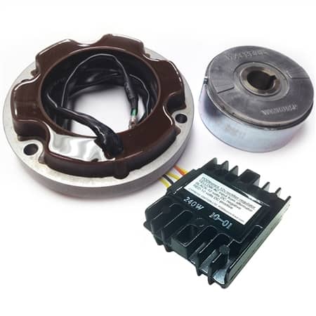
Emgo 3 Phase Alternator Kit
DOWNLOAD PDF FILE HERE: JRC 17-111 Instructions
Thank you for choosing Emgo products. Please read the following installation instructions to insure the maximum performance from your Emgo product.
First a word of caution: Installing this product requires advanced mechanical skill. If you are unsure of your ability to properly install this product we strongly recommend referring this task to a qualified technician.
Technical data for Emgo 3 phase charging system:
1. The alternator produces 3 phase AC current that is rectified to 14.2 volts DC by the PodTronic regulator
2. The regulator unit is polarity sensitive and can be severely damaged if connected to the battery in reverse polarity
Red is positive (+) and black is negative (-)
3. The unit is designed to operate with a battery. Do not disconnect the battery while the engine is running as damage to the regulator may result. This product is not suitable for operation without a battery.
4. The use of Resistor type spark plugs or 5000 ohm plug caps is recommended. Charging rates may be unreliable if these parts are not used.
Installation of the Alternator:
1. Remove battery connections to avoid electrical short.
2. Remove left hand exhaust system
3. Remove left foot rest
4. Drain primary oil and remove primary cover. Have a catch basin handy to collect the primary oil.
5. Remove the old rotor and stator. It is a good idea to replace the sealing rubber on the stator wires and the lock tab on the rotor nut. This is also a good time to inspect your primary drive chain.
6. Install the new rotor with the raised timing marks outward except on three cylinder models.
Special note for Trident and Rocket 3 owners: On some 3 cylinder machines it will be necessary to file down the raised timing marks to clear the timing gears. The back of the rotor becomes the front on 3 cylinder machines. The Emgo stator is thinner than the original on 3 cylinder machines.
This has no effect on the alternator output.
7. Install the new stator with the wires pointing outward to clear the primary chain. Make sure the wires will not come in contact with the primary chain.
On Triumph T140 models, it may be necessary to replace the stator studs with JRC 17-111A shorter stator stud kit.
8. Check the clearance between the rotor and stator using brass feeler gauges. The Emgo rotor has more clearance than the original Lucas components. Minimum clearance must be .008″ inch measured at 3 points opposite each other. Rotate the crankshaft 1/3 revolution and check the clearance again. Repeat the process once more. It is extremely important that there be clearance at all points. If the rotor rubs the stator even for a short time the rotor will be demagnetized.
FAILURE TO PERFORM THIS STEP COULD RESULT IN INJURY OR DEATH DUE TO CATASTROPHIC FAILURE OF THE COMPONENTS RESULTING IN LOSS OF CONTROL OF THE MOTORCYCLE.
9. Feed the stator wires through the appropriate hole in the inner engine case. Replace grommet at this time. Refit the primary cover using a new sealing gasket and refill the primary with the recommended fluid.
10. Disconnect the rectifier and zener diode from the wire harness. Tape the zener diode connection so as to avoid possible short circuit. Install the regulator/rectifier unit in a place that will allow cooling air to flow over the unit. On Triumph machines under the battery box is a good place.
Connect the 3 stator wires to the 3 yellow wires from the regulator. The red wire from the regulator is positive(+) and the black wire is negative(-).
On typical British motorcycles the positive (+Red) lead is grounded. In this case connect the red regulator lead to the chassis of the motorcycle as ground. Connect the negative black lead (-) to the center lead you disconnected from the old rectifier, typically a brown and blue or brown and white wire.
11. Check all wire connections to be sure they are tight and reconnect the battery. Always connect red to positive(+) and black or brown/white or brown/blue to negative(-}.
12. Your battery will be maintained by the charging system at 12.5 volts at a charge rate of 14.2-14.5 volts.
Emgo products are sold through quality motorcycle dealers throughout the world. JRC Engineering does not sell retail. JRC Engineering guarantees the Emgo 3 phase charging system
for a period of 1 year from date of purchase by the end user. If you have any problems with your Emgo alternator please contact your Emgo dealer.
JRC Engineering is not responsible for damage resulting from misuse of this product. Our liability extends to the Emgo components only and does not cover any other parts or labor. Any defective units will be repaired or replaced at our discretion.
Can Podtronic 3 phase be used without a battery?
I mounted a three phase stator on our test rig. Connected a Pod three phase regulator.
Measured DC output from the regulator alone, with a capacitor, with a load from a 21 watt bulb and connected to a battery.
Alone and with a capacitor the voltage was not stable.
Alone it would range in rotation 11.+, 14.+, 15.+ and 17 volts
With a capacitor it still ranged 14+, 15+ and 18ish volts
Without a capacitor a 21 watt bulb would barely light the bulb. The bulb would pulse quite slowly (even though motor turning 3450rpm)
With a capacitor a 21 watt bulb would light very bright (enough so that it would eventually blow) and pulse much faster.
With a battery the out put was stable at 14.7 volts. The bulb would light as one would expect with no signs of pulsing.
It seems like the unit is referencing the battery voltage to control output. Without a battery the unit doesn’t seem to know what to do and out put varies in a cyclical pattern 11+, 14+, 15+ 17+, and repeating this sequence over and over.
So no, the unit seems to be using more sophisticated control and needs to be used with a battery.