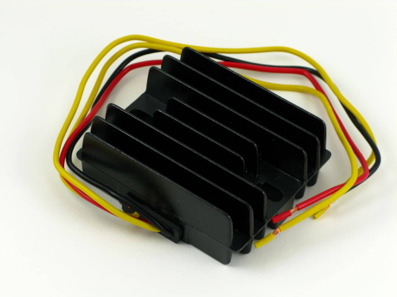
Our regulators boxes are an economical replacement for the Lucas rectifier and Zener Diode. They can be wired negative or positive earth. Can also be used on European and Japanese bikes with permanent magnet alternators not exceeding 200W.
These instructions will cover all two wire regulator rectifiers we sell: (PodTronic, Tympanium, Boyer, and Sparx).
“Two wire” refers to the number of alternator (yellow) input wires. Units with 2 yellow wires are single phase. If the regulator unit has three yellow wires it is known as three phase. See are tech article on alternator phase types for details.
On some earlier systems you may encounter an alternator with 3 or more wires. These are not three phase systems. A three phase system is easily identified by the 9 stator poles and 3 wires. Early stators employ 6 poles and 3, 4 or 5 wires. You can convert the 3 and 5 wire, 6 pole alternator to 2 wire with out much difficulty. This converts the motorcycle to 12V which will require updating the light bulbs. Especially important on the 5 wire ET system as they employ AC bulbs. There is no easy or straight forward conversion for 4 wire ET systems.
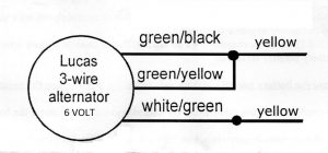
For 3 wire 6 pole alternators (6V) you can convert these to 12V by joining the green/black and green/yellow wires. The white/green will be the second leg. Or just run one of out 6V solid state regulators.
Installation is pretty simple:
- Mount the regulator module near the battery in an area that gets free flowing air. The aluminium body acts as a heat sink. It gets warm to the touch though does not get as warm as the factory zener diode. Modern regulators use a IC chip to switch on/off charging. Factory equipment shunts the excess power to a diode which converts this energy to heat.
- Observe if your system is Positive or Negative earth (ground). British bikes were generally: Negative ground till 1950, Positive ground 1950-78, and Negative 1979-On. From the factory.
- Disconnect the ground wire from your battery.
- Locate and remove or unplug the Zener diode and selenium rectifier. Zener: These can be found in a few locations: Between the fork legs on the finned heat sink, attached the alloy body of the airbox on OIF models, on an aluminium plate under the seat, or on the footrest mount plate on Norton. Rectifier: Stacked plates on a post under the seat.
- There are three wires connected to the selenium rectifier you just removed.
- Green/White and Green/Yellow which comes from the alternator
- The “hot” wire is usually Brown/White. This goes to the “hot” side of the battery. This is the opposite of your earth wire.
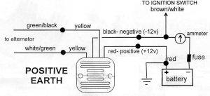
- Connect the Green/White coming up from the alternator to one of the yellow wires. The Green/Yellow wire goes to the other yellow wire
- If your system is Positive earth connect the red wire to earth (frame ground) and black wire is output to the negative battery terminal.
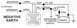
- If your system is Negative earth connect the black wire to earth (frame ground) and red wire is output to the positive battery terminal.
Be sure of your battery polarity! Other wise you will damage the regulator. On the regulator box Red is always Positive and Black is always Negative. Note the finned case is insulated from the wiring and not going to determine polarity. The wiring color codes are all that need your attention.
9. Now that you have verified everything is connected properly, reconnect the battery ground wire.
10. If the module gets warm, you have connected it backwards. Disconnect and recheck your wiring.
Diagrams:
Wiring without a battery:
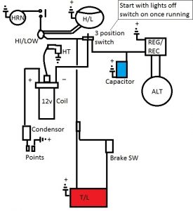
There are 3 brands of single phase Powerbox regulator or battery eliminator (similar to the old Mity Max units) These have a built in capacitor for running the ignition. To go battery-less you will need to have a way to start the bike with the lights off. Once the engine is running the lights can be switched on. Running low wattage bulbs makes a difference at low engine rpm. Our LED bulbs will be bright even while sitting at a traffic signal.
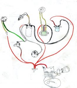
Or use a standard 2 wire reg/rec with the old 2MC capacitor:

SIMPLE BASIC DIAGRAM WITHOUT A BATTERY
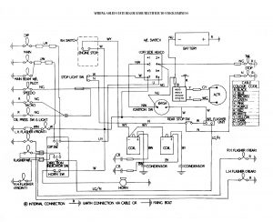
STOCK HARNESS WITH BATTERY