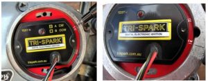
In Sept 2021 Tri-Spark introduced the Classic Twin-0006 which replaces the A and B types produced prior to 2022.
*Make sure you are using the correct instructions for timing. The static timing positions on the plate is reversed on the later units. This caused one dealer a great deal of grief.
Date codes: 2013-2016 will be engraved on the back side of the aluminium trigger plate . 2017-present (date on red side) will have a marked over the year to indicate date of manufacture.
Click here to view or download as PDF (Lates Twin 2021 on)
Click here to view or download as PDF (A and B Type Till 2021)
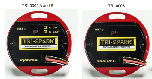
Tri-Spark – Classic Twin Installation Instructions TRI-0005 A and B (With revisions included covering TRI-0006)
Thank you for purchasing the Tri-Spark Classic Twin Ignition system for your Classic bike. For your own safety and success with the installation we strongly recommend that you engage a qualified technician to install your new ignition system. The following information is provided to assist them with the installation.
Manual Contents Page
Preparation 2
Remove old ignition parts 3
Rotor and stator installation 4
Coil wiring 5
Wiring diagrams 6-7
Static and strobe timing 8
Specifications 9
Self-test diagnostics 10
Troubleshooting tips 11
Warranty policy 12
Please note – The Classic Twin ignition is available in two versions which are not interchangeable. Instructions for both are included here – watch for the colour coding and follow the instructions for your version. See page 9 for more engine compatibility details.
TRI-0005A “A” for clockwise turning trigger rotor suits: Triumph unit construction twin engines, RE interceptor 2, 68 Norton Atlas
TRI-0005B “B” for counter-clockwise turning trigger rotor suits: Norton Commando, BSA unit twins, BSA unit singles, triumph unit singles.
TRI-0006 (latest) replaces “A” and “B” units. Use timing marks: “CW” for clockwise turning rotor, “AC” for counter or anti-clock.
Step 1: Preparation
Read all installation instructions before you begin. Disconnect the battery, remove fuse, seat, side cover, points cover, spark plugs, strobe timing port cover and rocker covers. Remove the condensers and ballast resistor and do not reconnect them to the electrical system – they are not required with electronic ignition.
Important: A general inspection and tidy up of all wiring including inside the headlight shell and rear mud guard is highly recommended. Inspection and testing of the charging system prior to installation is also highly recommended.
Caution: use the recommended Tri-Spark coils – wrong coils will damage. For Twins use two of our IGC-1006 six volt coils, 1.8 Ohm primary resistance. For Singles use our IGC-1012 twelve volt coil, 3.6 Ohm primary.
Alternative for twins is our IGC-2012 dual output coil, 3.6 Ohm primary.
Important: You MUST SWAP THE TERMINALS on the Red and Black/Yellow wires if you use the Classic Twin in a NEG
Step 2 – Remove the original points base plate and auto advance unit
The points plate is retained by the two pillar bolts. The wiring to the points plate should be disconnect from the points. The auto-advance unit is removed by threading in a correct sized bolt and giving this bolt a tap or by inserting a steel rod and gentle taping it around until the auto advance unit drops off it’s taper. Caution: It may be a tight fit.
Step 3 – Rotate the engine to correct timing position
With the engine in gear rotate the engine forward using the rear wheel until the correct strobe timing mark lines up with the pointer, one of the cylinders should be on its compression stroke. This should be the fully advanced timing position for your engine. For example 29 Degrees BTDC for Norton or 38 Degrees BTDC for Triumph. Consult your factory manual for details about timing your specific model.
Step 4 – Terminate the two black wires
Trim the points wires to the same length, cut back the black sheath if necessary to expose about 60mm of the black/white and black/yellow wires.
Adjust the wire route up near the coil area if necessary in order to pull through 80mm of wire into the points area.
Terminate the black/white and black/yellow wires with the bullet connectors (if in doubt see PDF for picture).
Step 5 – Installing the Tri-Spark rotor and Stator
Loosely install the stator unit so that the holes for the pillar bolts are in the center of the adjustment slots as.
TRI-0005A Clockwise only – TRI-0006 CW
Mark the engine casing adjacent the “A” line on the outer rim of the stator unit, then remove stator unit. “CW” on the TRI-0006.
Remove stator unit and install the Tri-Spark rotor with its two magnets inline with your mark.
TRI-0005B Counter-clockwise only – TRI-0006 AC
Mark the engine casing adjacent the “B” line on the outer rim of the stator unit, then remove stator unit. “AC on the TRI-0006.
Remove stator unit and install the Tri-Spark rotor with its two magnets inline with your mark as shown here
Install the Tri-Spark rotor using the correct socket head bolt for your engine. Two are provided (1/4 UNF and 1/4 BSF) for use with the earlier and later engine models. When tightening the bolt ensure correct torque and check the fit of the taper inside the cam.
Caution: shorten the bolt if it bottoms out in the threads.
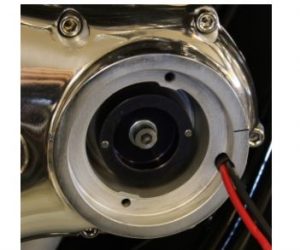
Once the rotor has been fitted check that the face of the rotor is back from the ledge that the stator unit sits on by two millimetres using a straight edge as shown in the following photograph. (2mm +/- 0.6)
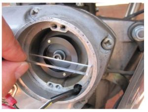
Check for end float in the cam and ensure that the rotor cannot move forward to close this air gap.
Install the stator unit using the original pillar bolts and washers. Use additional washers if the pillar bolts bottom out. Do not tighten the pillar bolts at this time – adjustment will be made later on.
The ring terminal on the red wire coming from the stator unit is to be held in place by the top pillar bolt as shown, except in negative earth installations. Please refer to the wiring diagram on the next page for negative earth connections.
Connect the black/white and black/yellow wires as shown in the photograph above forming the wires in a bend to reduce the strain on the wires caused by vibration.
Step 6 – Connecting the coil wiring on positive earth machines
The black/white and black/yellow wires that originally connected to the coils and condensers must be disconnected completely from the condensers and the coils as they now serve a new purpose. Also disconnect any other wires from the coils.
The black/white wire should be connected to the negative terminal of the closest coil or the most convenient coil. A link wire must be installed from the positive terminal of this coil to the negative terminal of the other coil. This should leave one coil with its positive terminal unconnected. This terminal should now be connected to positive frame earth (ground).
The black/yellow wire should now be linked to the “switched ignition” wire. This wire will vary in colour depending on the model. Please refer to your wiring diagram for the bike to locate the wire switched at the ignition switch and designated for the ignition system. Refer to the wiring diagrams on the next page for further details.
Important: For negative earth follow the alternative wiring diagram
Wiring Diagram – Tri-Spark Classic Twin Positive Earth and Two 6 volt Ignition Coils
Wiring Diagram – Tri-Spark Classic Twin Positive Earth and One 12 Volt Coil
Step 7 – Setting the timing statically using the LED
(Note timing procedure for the early 0005 units differ from the new 0006. Read the instructions carefully).
Note: The engine must be in its fully advanced timing rotation during this step. Once the wiring from Step 6 has been double checked, reinstall the battery and fuse and switch on the ignition.
Summary of timing procedure:
TRI-0005A Clockwise only – For 0006 see below
Begin by rotating the stator unit fully clockwise in the slots then rotate it slowly counter-clockwise to the position where the red LED on the stator unit just comes on. Tighten up the pillar bolts at this position and switch off the ignition. This procedure sets the timing to within just a couple of degrees of the final setting. The timing should be confirmed with a strobe light before riding.
This is the final step – replace all covers and parts that were removed for the installation process.
TRI-0005B Counter-clockwise only – For 0006 see below
Begin by rotating the stator unit fully counter-clockwise in the slots then rotate it clockwise to the position where the red LED on the stator unit just comes on. Tighten up the pillar bolts at this position and switch off the ignition. This procedure sets the timing to within just a couple of degrees of the final setting. The timing should be confirmed with a strobe light before riding.
Note: If the LED is on when the stator is fully counter-clockwise, the rotor will need to be moved slightly further clockwise.
TRI-006 type CW mark on plate
Begin by rotating the stator unit fully clockwise in the adjustment slots – the LED should be on. Now rotate the stator unit anti-clockwise to where the LED just goes OFF and continue rotating it a further 2mm. Tighten up the pillar bolts at this position and switch off the ignition. This procedure sets the timing to within just a couple of degrees of the final setting. The timing should be confirmed with a strobe light before riding.
This is the final step – replace all covers and parts that were removed for the installation process.
TRI-006 type AC (anti-clock) mark on plate
Begin by rotating the stator unit fully anti-clockwise in the adjustment slots – the LED should be on. Now rotate the stator unit clockwise to where the LED just goes OFF and continue rotating it a further 2mm. Tighten up the pillar bolts at this position and switch off the ignition. This procedure sets the timing to within just a couple of degrees of the final setting. The timing should be confirmed with a strobe light before riding.
Note: If the LED is on when the stator is fully counter-clockwise, the rotor will need to be moved slightly further clockwise.
Notes about strobe timing
Refer to your workshop manual for detailed instructions regarding strobe timing – these are intended as general notes only.
To check the ignition timing with a strobe light, warm up the engine and aim your strobe light at the timing marks. You should see an image of the timing marks that advances as the revs are increased. At 3500 RPM the image will appear to stop advancing. Watch for the fully advanced timing marks to align at 3500 RPM and faster to confirm the timing is correctly set.
If the timing marks do not align at 3500 RPM you must change the position of the stator unit by loosening the pillar bolts and rotating the stator unit slightly to the required position. This should be done with the engine stopped. Repeat the above.
If your engine does not have strobe timing marks you will need to rely on the static timing and any other techniques to ensure that the timing is set correctly.
Specifications
Nominal operating voltage: 12 volts (min 8V max 16V) positive or negative earth (ground)
Power consumption including coils: 3A Max (typically 2A)
Power consumption at idle: under 1 Amp
Coil circuit resistance range: 3.0 to 5.0 Ohms (3.0 absolute minimum)
Dwell time: 8 mS nominal with peaks on acceleration and starting
Advance range: 12.5 degrees cam or 25 degrees at the crank
Fully Advanced: at 3500 RPM
Starting range: up to 500 RPM
Idle stabilization range: 500 to 1200 RPM
Advancing timing range: 1200 to 3500 RPM
Operating temperature range: -20 to 100 degrees Celsius
Absolute maximum: 24 volts DC for 1 minute
Maximum load dump voltage spike: 180 Volts DC for 50mS
Air Gap (rotor to stator unit clearance): 2mm +/- 0.6mm
RPM range: 150 to 8000 RPM
Size: Stator unit 68mm diameter 10mm thick excluding wires
TRI-0005A Clockwise system for Triumph Bonneville T140, T140E, T140V, T120, T100, Tiger TR7RV, TR6, Norton Atlas, Enfield Interceptor series 2. 12 volt only with twin points including electric start
TRI-0005B Counter clockwise system for Norton Commando 750 and 850, BSA A50, A65, B50, B44, B25, Triumph Tiger cub, Enfield interceptor series 1. 12 volt only with single or twin points including electric start.
Using the built in self-test function
By switching the unit into test mode it is possible to check the operation of the stator
unit, trigger rotor, coils, HT leads and spark plugs.
Warning: the system is capable of sparking the coils in this mode – extreme care must be taken to ensure there is no risk of fire or electric shock that can arise from switching on the test mode. Make sure there is no fuel in the vicinity of the spark plugs. Keep children and pets well away.
We strongly advise engaging a technician to perform these tests in the safety of a fully equipped motorcycle workshop.
TEST 1: Start by removing the spark plugs from the engine and laying them on the cylinder head.
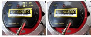
READ THE FOLLOWING CAREFULLY HOLD DOWN the test button very gently with the tip of a pen
WHILE SWITCHING ON THE POWER TO THE IGNITION (ignition key switch). The test button is located beside the word ‘TEST’ on the stator as shown.
The test button MUST be held down WHILE the power is switched on to begin the testing.
The spark plugs should begin sparking immediately at a rising rate for 10 seconds and then stop. The test can be repeated by pressing the test switch again. The LED should light during the 10 seconds while the system is sparking.
TEST 2: WITHOUT SWITCHING OFF THE IGNITION a second test should be performed to check the triggering of the position sensors in the stator unit by rotating the engine slowly until the red LED on the stator unit is seen to light. The LED should light when the magnet is between the “A” and “B” marks on the rim of the stator unit.
The LED lights to indicate that the magnets in the rotor are triggering the sensors in the stator unit.
The system is expected to function normally on an engine if BOTH tests pass.
EXIT TEST MODE – The ignition switch must be switched off to power down the stator unit in order to exit the test mode before attempting to start the engine.
Click here for the trouble shooting guide
General troubleshooting tips, installation notes and cautions
Take care! Do not probe around the wiring with the power on. Disconnect the
fuse before attempting any adjustments or disassembly.
Do not run the engine without all spark plugs connected as this can damage the
Tri-Spark system and/or the ignition coils.
There are two versions of the Tri-Spark Classic Twin: clockwise (A) and counter-clockwise (B). These are identified by a marking on the front label and are NOT interchangeable. Ensure that you have the correct system for your engine.
We recommend the use of spark plug suppressor caps with this system. Use 5k Ohm caps such as NGK LB05EP. Use Suppressor (resistor) caps or resistor spark plugs – not both together. An ‘R’ in the part number denotes resistor.
Ensure that the battery is fully charged and in good condition. If the battery dips
below 12 volts when the headlamp is switched on then it needs replacing.
Check that the air gap between the trigger rotor and stator unit is 2mm +/- 0.6
Check for 12 volts reaching the stator unit. Measure for 12 volts between the
RED and BLACK/YELLOW wires at the stator unit using a voltmeter.
Perform BOTH tests as detailed on the previous page. The system should
spark the coils for 10 seconds at the start of TEST 1.
Perform TEST 2 IMMEDIATELY after the coils stop sparking from test 1 WITHOUT switching off the ignition. Ensure that the LED lights in the firing position.
If the system passes test 1 and test 2 from the previous page it should be able to start and run the engine as these tests are designed to fully test the system.
If the engine runs but misfires at certain revs check out the charging system. Try running the system briefly with the alternator disconnected to see if that clears the problem.
Always try a fresh set of spark plugs. Most ignition problems are related to
fouled spark plugs. Try a new set right out of the boxes.
This is a wasted spark system – it fires both coils together therefore if a fault exists on one cylinder only it must relate to the coil, HT lead or spark plug on the faulty cylinder – not the ignition module in general.
Please note the above information relates only to the TRI-0005 Classic Twin
and should not be applied to any other product.
Tri-Spark Classic Twin Warranty Policy
The Manufacturer Tri-Spark extends a Warranty to the original purchaser of this kit covering the Stator Unit and Rotor components of the system (not sundry items) under normal use for a period of three years from the date of purchase . Only those parts which are deemed by Us to be defective due to faulty materials or workmanship in manufacturing shall be repaired or replaced under this Warranty. Conditions apply.
Limitation of liability
It is the sole responsibility of the purchaser to determine the suitability of the product for a particular installation or purpose. Under no circumstances shall the Manufacturer Tri-Spark be liable for any consequential, special, incidental, direct or indirect damages arising from the use or lack of ability to use this product. The Manufacturer ’s liability under this Warranty is limited to the replacement of the product or its parts and no other obligations, expressed or implied are assumed by the manufacturer Tri-Spark. A refund option is not offered as part of this Warranty.
Conditions
This Warranty will be void if the product or parts have been in any way misused, abused, altered or installed incorrectly as determined by Us.
This Warranty will be void if faults are caused by but not limited to: 1) operation with incorrect coil circuit resistance (under 3 ohms)
2) the rotor contacting the stator unit as evidenced by circular scratches 3) bending, cutting or any other physical damage to the parts 4) the ingress of oil, water or other liquid into the parts 5) exposure of the parts to solvents or chemicals 6) damaged or broken wires connecting to the parts
7) any modification to the parts not authorised by the Manufacturer
8) any electrical damage to the parts caused by voltage spiking from the battery, charging
system, jump starting or any other devices connected to the electrical system.
The manufacturer reserves the right to charge a testing fee of $45AUD and a return freight fee of $30AUD in cases where parts returned to Us are found to be functional.
The purchaser is responsible for the cost of freight, customs duties, taxes and tariffs to and from the point of purchase where the part or parts shall be assessed for possible replacement. Recorded delivery is recommended to protect against loss.
To make a claim under this Warranty the purchaser is requested to contact the point of purchase for instructions. The purchaser may be asked to perform certain tests to determine the nature of the problem. The suspected faulty part(s) must be returned with proof of purchase and a detailed account of the problem experienced to the point of purchase or the Manufacturer for testing and possible replacement. Returned parts must be sent with freight prepaid. Recorded delivery is recommended.
Statutory rights
Your statutory rights are unaffected. Additionally, if any statement herein is deemed to be invalid for any reason then only that statement shall be deemed invalid. The Laws of South Australia shall apply to purchases made directly from the Manufacturer.
TRI-0006 Revised Sept 2021