PAZON INSTRUCTIONS OTHER IGNITIONS
Click on the part number to open:
Fault Finding
Smart Fire Dual Plug
Below covers the popular PA2 Ignition:
Click here to view and download as PDF file
PAZON SURE FIRE ELECTRONIC IGNITION FOR UNIT CONSTRUCTION TWIN CYLINDER MOTORCYCLES
WITH POINTS IN THE SIDE CASING & 12 VOLT ELECTRICS POSITIVE OR NEGATIVE GROUND SYSTEM TYPE: PA2
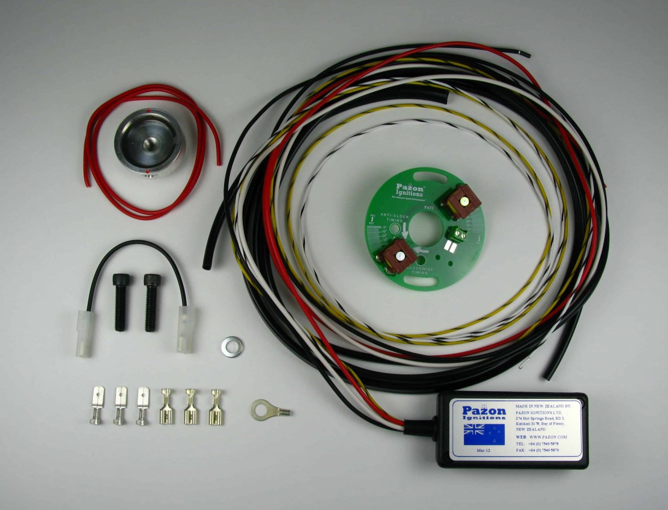
Sure-Fire System Contents :
IGNITION MODULE• TRIGGER ASSEMBLY • MAGNETIC ROTOR • ¼” BSF BOLT • ¼” UNF BOLT
• BLACK COIL LINK WIRE • RED GROUNDING WIRE • CRIMP CONNECTORS & INSULATORS • LARGE & SMALL CABLE TIES
• CABLE TIE ADHESIVE MOUNTING BASE • ¼” FLAT WASHER
WARNING: RISK OF ELECTRIC SHOCK ALWAYS TURN OFF BEFORE WORKING ON THE SYSTEM
BEFORE FITTING, PLEASE READ THESE INSTRUCTIONS CAREFULLY
Sure-Fire Installation Instructions :
1. All connections must be of the highest quality, use crimped or soldered connections; twisted wires will not give a satisfactory operation.
2. Remove the petrol tank and/or seat to gain access to the ignition coils, condensers and wiring.
3. For safety, disconnect the battery (preferably both terminals).
4. Remove timing cover. (The Atlas engine has the points housing behind the cylinder head).
5. Disconnect the two wires (usually black-white & black-yellow) and remove the contact-breaker plate. At the other end, these two wires must be disconnected from the ignition coils & condensers. The condensers are no longer required and can be removed. They should not be connected to the electronic ignition system.
6. Remove auto-advance unit.
7. Disconnect the remaining wires from the ignition coils. These come from the ignition switch supply. On the Norton Commando, remove the white-blue wire from the ballast resistor between the two ignition coils; the ballast resistor is no longer required. The colour of this ignition supply wire may be different on some machines; if so check using a test lamp or meter to find the live wire when the ignition is switched on.
8. Find a suitable place for the ignition module, preferably near to the ignition coils. Secure the ignition module to the frame using one or more large cable ties. An adhesive mounting base is provided; this can be affixed to the underside of the module and the cable tie passed through and around the module and frame. Do not completely wrap the module in foam rubber. This can cause the unit to overheat.
9. Using the black coil link wire, connect the negative (—) terminal of one ignition coil to the positive (+) terminal of the other ignition coil. See figs. 1/2 on page 7.
10. Take the black wire from the ignition module, cut to length and fit an insulator and female spade connector to the end. Connect to the negative (—) terminal on ignition coil #1. See figs. 1/2 on page 7.
11. Take the red wire from the ignition module, cut to length and fit an insulator and female spade connector to the end. Connect to the positive (+) terminal on ignition coil #2. See figs. 1/2 on page 7. 12. For NEGATIVE GROUND electrics go to step 15. 13. For POSITIVE GROUND electrics (standard):
Take the white wire from the ignition module, cut to length and fit an insulator and male spade connector to the end. Connect to one of the negative ignition feed wires previously removed in step 7 (white-blue wire for Norton Commando). The other wire (if fitted) is spare and should be covered with insulation to prevent shorting to the frame etc.
14. Take the red grounding wire, fit an insulator and female spade connector on one end and connect to the positive (+) terminal on ignition coil #2. Cut to length and fit a ring terminal on the other end and connect to a good grounding point on the frame, ideally the battery positive (+) terminal. For the Norton Commando, the grounding tag on the end of the condenser pack can be used (fit a female spade connector to the end of the red grounding wire). See fig.1 GO TO STEP 17 .
15. For NEGATIVE GROUND electrics: Connect one of the positive ignition feed wires previously removed from the ignition coils in step 7 to the positive terminal of ignition coil #2. See fig. 2
Any other wires are spare and should be covered with insulation to prevent shorting to the frame etc.
16. Take the white wire from the ignition module, cut to length and fit a ring terminal connector to the end. Connect to a good grounding point on the frame, ideally the battery negative (—) terminal. For the Norton Commando, the grounding tag on the end of the condenser pack can be used (fit a female spade connector to the end of the white wire). See fig. 2
17. Remove the two sleeved wires (black-white & black-yellow), previously disconnected in step 5.
18. Feed the two sleeved wires (black-white & black-yellow) from the ignition module down to the timing cover, in place of the original wires. If you would prefer not to remove the original wires, they can be reused with the electronic ignition. If so, take the white—black & white—yellow wires from the ignition module, cut to length and fit two insulators and male spade connectors to the ends. Connect these to the two wires removed from the coils in step 5, as follows: white—black to black—white; yellow—black to black—yellow (colours must match).
19. Remove timing inspection cover from alternator side of engine. Set engine to the full advance timing mark on the compression stroke (note: the other cylinder will be on the exhaust stroke). Either cylinder can be used, since both fire together (wasted spark system). If a timing mark is unavailable, the engine will need to be set using either a dial gauge down the bore or a degree disc. See table 1 (page 8) for the recommended full advance figures for engines in a standard state of tune.
20. Fit the magnetic rotor into the end of the camshaft, using the ¼” washer and one of the two bolts provided (UNF for Triumph, BSF for Norton). Finger tighten only at this stage. The magnetic rotor centre thread (metric M8) is provided for attaching a puller, if the rotor should need to be removed for engine servicing, etc. Some Triumph models may have a locating pin fitted into the end of the camshaft. If this applies to your bike and the pin fouls on the rotor, you will need to cut a small notch into the taper of the magnetic rotor, to allow it to seat fully into the camshaft. With one of the red dots positioned under the trigger clockwise timing hole (see next step), mark the position of where the locating pin will be on the rotor taper. Then remove sufficient metal using a file or small hacksaw.
21. Hold the ignition trigger assembly in the contact-breaker housing, positioned midway on its adjustment slots (the slots will normally be positioned at approximately 6 and 12 o’clock). Turn the magnetic rotor by hand until the red indicator dot aligns under the appropriate static timing hole in the trigger. This must be done without turning the engine. The appropriate timing hole is determined by the direction of rotation of the camshaft. The timing holes are marked on the trigger “Clockwise Timing” & “Anti-Clock Timing”. See figs. 3 & 4 (page 9). For the Norton Commando, the magnets should be lined up approximately horizontal with the “Norton” stamp on the timing casing of the engine. To determine the correct timing hole for your machine, see Table 1 (page 8).
22. Tighten the rotor bolt with a 3/16” allen (hex) key and re-check engine position and rotor alignment.
23. Insert a small cable tie into the two holes in front of the connector block on the ignition trigger. Fit the ignition trigger (in the place of the removed contact-breakers) with the original pillar screws.
24. Allow a minimum of 50mm/2” of excess wire between the trigger and ignition module. This is especially important on rubber-mounted engines (e.g. Norton), where engine vibration can lead to internal fracturing of the trigger wires. Route the white-black & yellow-black wires from the hole in the timing cover around to the connector block on the ignition trigger and cut to length. Slide over a small length of sleeving. With a pair of wire strippers/cutters, carefully remove 4-5mm of insulation from the ends of the two wires. Insert the yellow-black wire into the left-hand screw terminal and the white-black wire into the right-hand screw terminal. The connector block terminals are marked on the trigger plate “Y/B” and “W/B”. Tighten the two screws. Secure the wires and sleeving with the cable tie, fitted in step 23. If preferred, the two wires can be soldered directly to the trigger using the two solder pads provided in front of the connector block. It is essential that these two wires are connected the right way around for correct operation of the ignition system. Reversed connections will give very retarded ignition timing .
25. Re-check all connections are good and tight; any loose crimps should be removed, slightly closed up and refitted, or preferably replaced.
26. Refit tank, fuel lines, battery & seat.
27. Start engine and run for 4-5 minutes to warm up. Using a white light strobe, time the engine to the full advance mark (previously used in step 19) with the engine running up to 4000 rpm. If running in, you may strobe time at 3000 rpm to the full advance figure less 2°. Adjust the timing by making very small movements of the ignition trigger on its slotted holes; moving the trigger by 1° is equivalent to 2° of the crankshaft. The trigger has calibration marks (equivalent to crankshaft degrees) marked on the outer edge to assist with the timing adjustment. When using a strobe light, you may see a small amount of advance above 4000 rpm, this is normal. For high revving engines you may wish to strobe at 5000+ rpm for best results. To advance the timing, turn the trigger against the direction of the magnetic rotor. To retard the timing, turn the trigger in the same direction as the magnetic rotor. In the unlikely event that the timing cannot be obtained before the end of the adjustment slots, the magnetic rotor will need to be slackened off and repositioned slightly. If no timing mark is available, road test the machine and adjust (if necessary) for optimum performance.
28. Refit timing/contact-breaker cover.
29. The timing is now set and requires no further adjustment. However, please note that for satisfactory operation of this ignition system it is important that the wiring, ignition coils, switch, battery, h.t. leads, plugs and plug caps are in good order.
POSITIVE GROUND SYSTEM WIRING DIAGRAM
NEGATIVE GROUND SYSTEM WIRING DIAGRAM
TIMING HOLE FULL ADVANCE TIMING DEGREES
TRIUMPH TWIN CLOCKWISE 38°
BSA TWIN ANTI-CLOCKWISE 34°
NORTON COMMANDO ANTI-CLOCKWISE 31° (28° STANDARD*)
NORTON ATLAS CLOCKWISE 31° (28° STANDARD*)
* STANDARD REFERS TO ORIGINAL IGNITION SETTING WITH MECHANICAL ADVANCE
NOTE: IF USING A DEGREE DISC ATTACHED TO THE CAMSHAFT , THE FULL ADVANCE FIGURE READING ON THE DISC MUST BE HALVED. E.G. FOR 38°, SET ENGINE TO T.D.C., ZERO DEGREE DISC AND ROTATE ENGINE BACKWARDS UNTIL DEGREE DISC HAS TRAVELED 19°
Sure-Fire TECHNICAL DATA
Ignition Module (Part# PAM2)
Minimum Supply Voltage: 10 Volts DC Maximum Supply Voltage: 16 Volts DC
(Reverse Polarity Protected)
Maximum Ignition Coil Peak Primary Voltage: 400 Volts (Regulated) Maximum Ignition Coil Secondary Voltage: Ignition Coil Dependent
Current Draw (Static): 0.05 Amps Max. (Ignition Coils Off) Current Draw (Dynamic): Typically 2 Amps (Coil Dependent) Maximum Ignition Coil Current Draw: 5 Amps
Ignition Coil Turn Off (Engine Static): < 3 Seconds (Typical) Minimum Cranking Speed: 100rpm (Typical)
Maximum Switching Rate: 10,000 Sparks/Minute (Typical)
Ignition Trigger (Part# PAT2)
Trigger Type: Twin ferrite core Configuration: Series connected Trigger coil resistance: 55 Ω @ 20°C. Total trigger resistance: 110 Ω @ 20°C. 2-Way Connector Block Wire Size: 0.75mm² max.
Ignition Magnetic Rotor (Part# PAR2)
Material: Aluminium + inner steel ring Magnet Polarity: South poles both face outwards
Ignition Coils
When using the standard arrangement of two ignition coils (whether 12 Volt or 6 Volt), they must be connected in series, as shown in the wiring diagrams on page 7. Do not connect the coils in parallel.
For low compression ratio engines (less than 9:1), two 12 volt coils connected in series can be used, but we strongly recommend running with two 6 volt coils connected in series or one 12 volt dual output coil with a primary resistance of 3 to 4.5 ohms.
CDI type and some electronic ignition coils are incompatible with this system; for suitability check the primary resistance is 3 ohms or more (measure across the + and — terminals with a multimeter).
Ignition coils can develop a short circuit to ground through the case, especially if the clamps are too tight (common on the Norton Commando). This can cause overheating of the affected coil and can also produce misfiring/bad running on one or both cylinders. Slacken the clamps and examine the coil casing for heavy crease marks. If in doubt replace the coils.
Recommended ignition coils (available from PAZON) for this system are: 2 x IC06 6 VOLT PVL SINGLE OUTPUT COIL (LUCAS 17P6 TYPE)
or
1 x IC05 12 VOLT DUAL OUTPUT COIL (4.2 OHM PRIMARY) 1 x HSK HEATSINK KIT FOR IC03/IC05/IC10
or
1 x IC10 12 VOLT DUAL OUTPUT COIL (3 OHM PRIMARY) 1 x HSK HEATSINK KIT FOR IC03/IC05/IC10
HT Leads, Spark Plugs & Plug Caps
Always use copper cored ht leads. Do not use carbon-fibre (resistive) leads.
Provided you have the correct grade of plugs for your engine and that they are in good order, there is no need to change them when fitting this system. The spark plug gaps can be left as standard, as a guide 0.025”- 0.028” should be sufficient.
We recommend fitting NGK 5K resistor (suppressor) type plug caps (or
similar good quality make), but you can also fit non-resistor caps.
General Data/Troubleshooting
This system can be adapted to work on many types of engine, provided that the required firing interval is every 360° crankshaft / 180° camshaft. This ignition is of the wasted spark type, i.e. both plugs spark at the same time, every turn of the engine. One plug will fire on the compression stroke and the other will fire on the exhaust stroke (the wasted spark). Since both plugs spark at the same time, bad running/ running on one cylinder can only be due to a faulty plug, cap, ht lead, ignition coil or mechanical problem, not the ignition module or ignition trigger.
Wiring should be cut to the correct length. Excess wire should not be coiled up; this can affect the correct running of the ignition system. Where possible the wires from the ignition trigger should be run separately from the rest of the wiring loom, especially the alternator stator wiring.
The frame/chassis must act as an electrical return (ground/earth), whether positive or negative ground. If the engine is rubber mounted a good ground/earth strap must be provided.
This system can be run without a battery, using a rectifier, zener diode and capacitor (or electronic rectifier/regulator), but note that kick-starting may be more difficult. An external capacitor (Lucas 2MC or similar) may be required to aid starting.
The system can also be run total-loss from a battery only (e.g. for racing applications).
The Sure-Fire ignition module features a simple self-test facility for producing sparks without turning the engine.
• Disconnect the ignition trigger wires (w-b & y-b) from the trigger. • Switch ignition on.
• Take the trigger wires, touch together and open, approximately
once per second. Both plugs should spark at the same time.
• If only one plug produces sparks, check the coil, lead, cap and
plug.
• If there are no sparks, check battery, switch, grounding, wiring,
connections & ignition module.
• Continuous sparks without turning the engine indicates a poor supply to the ignition; check battery (bad cell), switch, grounding, & connections.
Terms & Conditions and Warranty
• Use of this product indicates your acceptance of this notice.
• The product design & literature is Copyright © PAZON IGNITIONS LTD. 2005-2011, and
is protected under international copyright, trademark & treaty provisions.
• To provide the best ignition systems possible, PAZON IGNITIONS reserves the right to
alter and improve the specifications of its products without prior notice.
Ignition Systems
• Pazon warrants to the original purchaser that the Pazon Ignition System be free from defects
in workmanship & parts under normal use for a period of 7½ years from date of purchase.
Ignition Spares
• Spares are defined as item(s) not purchased as part of a complete ignition system. Pazon
Ignitions warrants to the original purchaser that these item(s) be free from defects in workmanship & parts under normal use for a period of one year from date of purchase.
• Ignition coils will only be covered by the warranty if it can be proved that the fault is due to
a manufacturing fault within the coil.
Limitation of Liability
• In no event shall Pazon Ignitions liability related to the product exceed the purchase price
actually paid for the product.
• Neither Pazon Ignitions nor its suppliers shall in any event be liable for any damages
whatsoever arising out of or related to the use or inability to use the product, including but not limited to the direct, indirect, special, incidental or consequential damages, or other pecuniary loss.
• This warranty will be void if the product or parts have been altered, damaged, abused or
installed incorrectly.
• This warranty will be void if parts supplied by Pazon Ignitions are used with other makes of
ignition. Your statutory rights are not affected.
Warranty Claims
• To make a claim under warranty, the product must be returned to PAZON IGNITIONS or its
authorized representative, with a copy of your receipt (or evidence of date & place of purchase), within the warranty period.
• Include a detailed description of the problem and why you believe there is a fault within the
ignition system.
• The system must be returned postage paid. Proof of posting is not proof or receipt, therefore
we recommend using a recorded mail service.
• Upon receipt we will thoroughly test the returned items and repair or replace any items
found to be faulty and covered by the warranty.