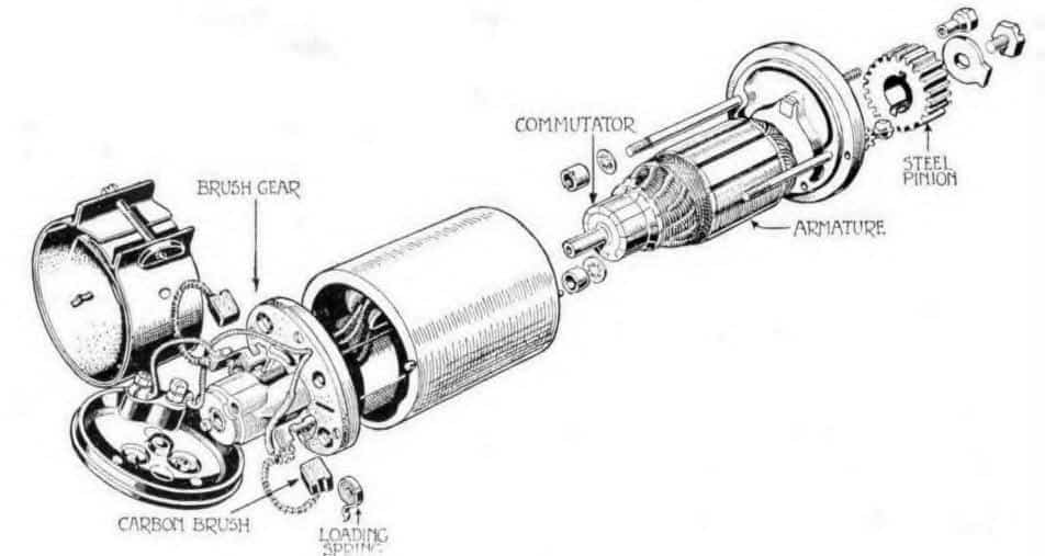
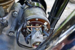
The Lucas two brush Dynamo (generator) was fitted to most British motorcycles from the late 1930’s through the early 1960’s The dynamo is a cylindrical affair located on the front of most Pre-Unit twins or on top of the Magdyno on most B models. Understanding how the Dynamo works will make your British motorcycling experience more satisfying and riding at night practical.
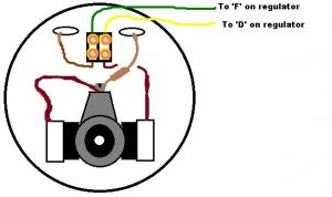
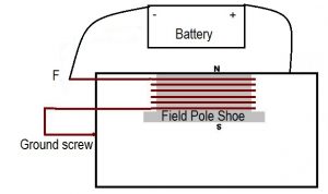
The Dyno works in this manner. Battery voltage is monitored by the voltage control box. When battery voltage drops below 6.3 volts (on 6v units) a set of contacts in the regulator close (modern regulators replace the contacts) and sends battery voltage to the field coil of the dynamo. This creates an electro-magnetic field in the field coil. As the armature windings rotate through the magnetic field current is induced in the armature windings. This is transmitted to the regulator where another set of contacts that regulate current to the battery and electrical system.
There are two basic types of Lucas dynamo. The model E3H , easily identified by the single large screw securing the pole shoe. The E3H puts out 45 watts and is stamped on the case with E3H. The later 60 watt unit is the E3L (the field coil is secured by 2 screws on these units). It is important to know what type you have in order to select the appropriate load your dynamo can service. If you install a 45W headlamp and 21W tail lamp with a 40W dynamo it will be unable to keep up with the demand resulting in dim lights and a discharged battery. Factory recommendations were for a 6 volt 24 watt headlamp and 6 volt 3 watt tail lamp bulbs along with 1.3 watt instrument bulb for a total of 28.3 watts with the 40W dynamo. As you can see the demand is less than supply so the battery remains charged and the lights are relatively bright. The same can be said for the 60 watt unit but you may run 36W headlamp and 6W tail lamp and 2W instrument light with sufficient current to keep the battery fully charged. This would be the first place to look if your battery is becoming discharged during use.
The E3M uses a bushing on the commutator end while the E3L uses a miniature ball bearing. It is vital these bearings are lubricated. The drive end of the Dynamo has a bearing as well. The Unit must be dismantled to grease this bearing. On A10 and Triumph Dynamos there is an oil seal that keeps grease in the bearing. After long service it is a good idea to renew this seal (Lucas# 188614) and grease this bearing. Magdyno units have a slinger to keep grease in the bearing. It is also vital that the Dynamo case be well grounded to the engine cases. If the dynamo case has been painted remove a small patch of paint to ensure a good ground.
You can test Dynamo output in this way: (We assume positive ground for the following tests; reverse the connections for negative ground systems).
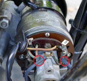
Remove the D and F connections at the dynamo and bridge the dynamo terminals with a short piece of wire. Using a volt-ohm meter on the 50 volt scale, or a 6v bulb with test leads, connect the negative terminal to the bridge wire on the dynamo and the positive terminal to the dynamo body. Reverse connections for negative ground bikes such as Vincent and pre 1950 British machines.
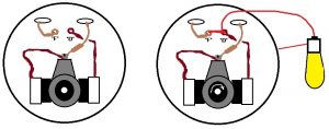
Start the machine and bring to a high idle. The volt meter should rise quickly to 7-10 volts or the bulb should light brightly. DO NOT REV the engine to get higher output. It is possible to damage the dynamo with it wired in this way if the engine RPM exceeds 2000. If no reading is obtained try cleaning the commutator with contact cleaner or WD40. Do not use flammable cleaners such as carburetor spray. You may use a bit of very fine emery cloth to clean corrosion from the segments also. Next disconnect the jumper wire and “flash” the field by momentarily flashing a jumper wire from the negative battery terminal (positive ground) to the F terminal of the Dynamo. Do not hold the jumper wire there but just arc it quickly 2-3 times. This will re-magnetize the pole shoe of the Dynamo. The Dynamo depends on residual magnetism in the field shoe to start the magnetic field. After sitting for long periods it is possible that the field shoe will have lost it’s magnetism and this will restore it.
Reconnect the jumper wire and check again for output. Note; Some pattern armature brushes have proven to build up a non conductive layer on the working face, they may look fine but will not conduct current from the armature. Always fit genuine Lucas brush sets (Lucas #200737 for E3L).lt is also possible that after very high mileage the mica insulators between the commutator segments will be standing proud of the brass segments. These may be eased down with a bit of hack saw blade until they are .020 inch below the commutator segments.
If a reading of 1/2, volt is registered it is possible the field winding has failed. If the reading is 1 1/2 to 2 volts it is possible the armature has failed. In either case the Dynamo must be removed from the machine for further testing.
With the Dyno removed but with the jumper wire still in place try to “motor” the Dynamo. Clamp the Dynamo in a vise and then connect the positive terminal of a 12 volt battery to the Dynamo case. Connect the negative battery lead to the bridge wire between the Dynamo D and F terminals. The Dynamo should motor (spin) in the direction the unit turns on the machine. If the direction of rotation is reversed then swap the brushes in their holders and try the unit again. It should motor in the desired direction. If you needed to reverse the brushes it is possible the unit will now work. Refit to the machine and recheck output as described above. If output is still low you will need to dismantle the unit for further tests.
To dismantle remove the commutator end cover and remove the brushes. Check the condition of the brush springs. These should hold the brushes in firm contact with the commutator. Disconnect the field coil leads. Remove the two long bolts that hold the generator together. The commutator end and bearing housing should be a tight fit. gently pry it off. Slide the Dynamo body off the armature. Holding the armature securely remove the bolt or nut holding the drive gear/sprocket. The A 10 uses a taper to hold the sprocket and can be very stubborn to remove. Use a gear puller for this. The Magdyno and most others are a straight shank with two keyways and are easily pried off. Remove the threaded ring under the drive gear and gently drive the armature out of the drive end cover. You can do a test of the field coil (the coil attached to the main body) by connecting a 6 volt battery in series with a 6v 3w bulb and the field coil wires. If the bulb doesn’t light the field is open and must be replaced. If the bulb is very bright when connected through the field then the field is internally shorted and must be replaced. The bulb should be a bit dimmer than when connected straight to the battery due to resistance in the field coil windings.
To test the armature a “growler” is needed, however a static test with a 6v 3w bulb can help. Using the same 6 volt battery and 6v 3w bulb, or a Volt-ohm meter, check for continuity between each commutator segment. The bulb should light brightly between any 2 segments. The bulb should not light between any segment and the armature body. If there are segments that fail the continuity test it is possible the field winding solder joint is at fault. Try re-soldering the wire where it joins the commutator segment. Failure of the bulb to light means the armature is faulty. If the bulb lights between any segment and the body of the armature it is internally shorted and replacement is needed. Do not attempt to straighten a bent armature or reattach loose commutator segments, it is false economy and will result in catastrophic failure. Reassembly is reverse of disassembly as they say. Make sure to fit the locking washers on the through bolts that hold the dynamo together. These tend to come lose and if they do the dynamo will be a complete write-off.
Bill Getty