Lucas Energy Transfer (ET) ignition unraveled

Lucas AC or Energy transfer ignition was used on many competition motorcycles among them the BSA B44E, B50MX and Triumph models T20M Cub, T100C , TR6C and most famously the T120C or TT Special. Many of these bikes have been converted to DC coil ignition but if you are fortunate enough to get a bike still equipped with ET ignition and it doesn’t start of runs poorly don’t despair, there is hope, so don’t phone home just yet!
First off this is not an in depth discussion of theory or an engineers description of how this works, it is a practical guide gleaned from years experience with this mostly reliable ignition system.
Identification of components
The ET ignition has some parts particular to this type of ignition that look the same or similar to battery coil (DC) ignition but are not interchangeable.
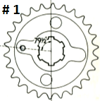
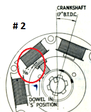
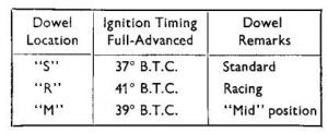
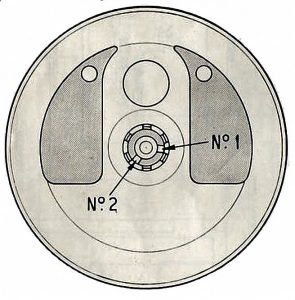
A. Alternator rotor can be identified by the 3 holes in the back marked “S” meaning standard, “R” standing for Racing and “M” for mid position. The rotor engages a pin in the engine sprocket on most Triumph and BSA twins. For most applications the “S” hole should be used. If the holes are not marked then use the hole closest to the rotor keyway. Twins do not use a rotor key! If you have removed the engine sprocket it is important that it be installed on the crankshaft in the proper position. With the pistons at top dead center the pin engaging the rotor is as per illustration #1. With the crankshaft turned to 17 degrees before Top dead center the magnets on the rotor should be about 1/16” ahead of the pole on the stator as shown in illustration #2. Use the peg holes (S,R,M) on the rotor to get this alignment as needed. T20 Cub uses a key and, in most cases, has 2 positions:
T20 Crank diagram (Right hand side of page)
No 1: (@ 3 o’clock ATDC ) Is for high compression engines and engines with high-lift camshafts. No 2: (@ 7 o’clock ATDC) Is for low compression and standard cams. Low compression (7:1) pistons are easily identified by shining a small flashlight down the spark plug hole. Low compression T20 pistons have a flat top. Higher compression will have a slight dome (9:1).
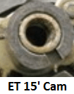
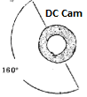
B. The advance unit for ET ignition has only 5 degrees of advance. It will be marked on the back with this number. The DC ignition advance has either 10 or 12 degrees of advance and will not work for ET ignition. Another way to tell is the points cam profile. The ET cam has a single cam lobe that opens the points for 15 degrees of rotation. The DC cam opens the points for 160 degrees of rotation. ET cam on the left has very short duration of points opening, DC cam on the right has much longer opening.
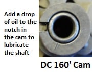
 (Note: use an ET cam for running without a battery on DC ignition bikes and starting will be greatly improved at the expense of high RPM performance. Great for desert sleds on BSA/Triumph singles) Be sure also that the advance advances in the right direction. The cam should turn against the springs in the direction of rotation. Triumph twins advance clockwise, Norton and BSA advance counter clockwise
C. Coils. The ignition coils for ET ignition are completely different than DC ignition. The original Lucas coils had a brown shellac covering that tended to shrink and crack with age. These often will work even if cracked badly but modern coils are available from Emgo that work perfectly even if they don’t look like the originals. Take special care however as the original Lucas coils use a solid brass wire for grounding 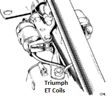 that is easily broken off where it enters the coil body. Emgo coil (45149R, Emgo 24-71532) on left, cracked original Lucas on right. The original coil pictured actually worked fine even in the condition pictured.
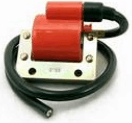
 Note that there is a condenser attached close to the coil as well. This is a must for the system to work. Lucas number 60410181. It is recommended you replace this part.
D. The alternator stator was supplied in several configurations: 5 wires for twins, 4 wires for singles. Refer to our tech article on Lucas alternators for details regarding identification.
Energy Transfer continued
1. Wire connections.
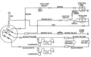
It is vital that the red lead from the alternator be well grounded. Also if using a twin cylinder alternator on a single cylinder machine the Black/White lead must be grounded and the Black/Yellow attached to the coil. If these are not well grounded you will not get any spark. The Brown /blue wire is for lighting and the brown wire is for the brake lamp. Be careful when fitting lights to the machine. The hi/low beam switch must be a special type that keeps one beam lighted while changing to the other beam (Lucas 31620) , If you use a conventional switch then when switching beams a voltage spike can occur and blow the tail lamp bulb. Then when the headlamp bulb engages it will also fail and then when shifting to the other beam it will also fail. It should be noted that ET systems use low wattage 6v bulbs. A 24/24W bulb (Lucas 166) must be used in the headlamp. Tail lamp uses a 6v 6/18W special bulb. Fitting higher wattage bulbs will make the lights very dim.
Twins:
Singles:
Color codes vary slightly between OEM Lucas and New production Emgo units. This should answer any questions regarding color codes
REPRODUCTION EMGO STATOR COLOR CODES:
LUCAS/ EMGO
Red – Red
Brown – Brown
Brown/Blue – Blue
Black/Yellow – Black/Yellow 2 of these
Black/White – Black/Yellow (both points circuit wires are black/yellow)
Some singles will have 4 or 5 wires. This diagram shows the Triumph Cub 3 wire ET. The 4 wire would have an additional brown lead for the tail light as on the twins. Single cylinder 5 wire stator has an additional black/white or black/yellow wire. To function the additional black/white lead must be grounded or joined in a common connection with the red stator wire. Click here for the service bulletin.
2. Setting the points gap and ignition timing.
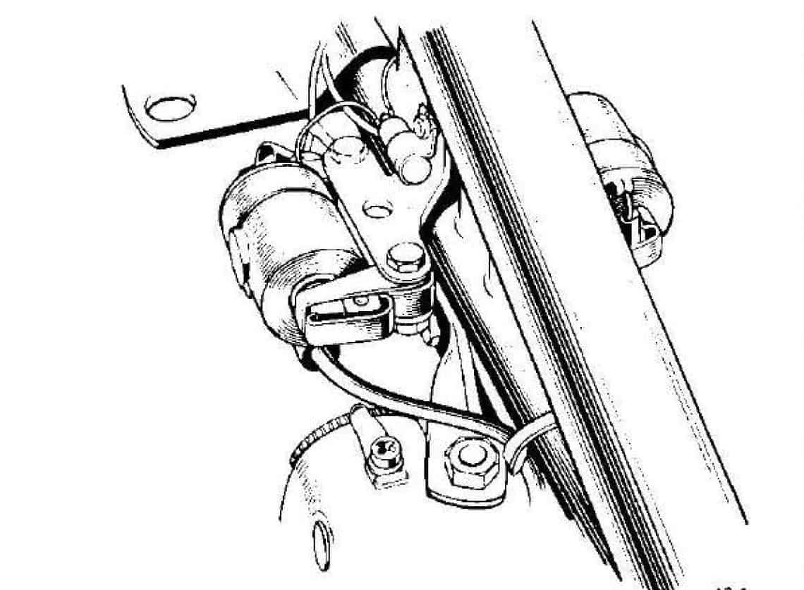
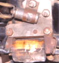
A. It will be noted that the 4CA points plate also has a pair of condensers fitted. Be sure that the 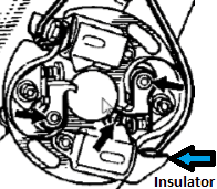 points faces are clean and flat. If in doubt replace them (54415803). Make sure the points spring are not touching the inside of the points cavity also. Make sure the cardboard insulators are in place (see arrow) and add a drop of oil to lubrication points pivot (arrows over points plate). Replacement condensers are available (54415803) however they are slightly longer than original and can be hard to fit in the points cavity. If you have replaced the condensers by the coils you should be alright.
B. Remove both spark plugs. Rotate the engine until the rubbing heal of the points lines up with the scribed mark on the points cam. Set the gap at .015” inch and do the same for the other side. Now using a long screwdriver with a thin shaft insert the blade into the plug hole and slowly turn the engine over until the pistons are at the top of the stroke. It is helpful to have the rear wheel off the ground and to make fine adjustments with the bike in gear and moving the rear wheel. Don’t worry if it isn’t exact. Now make a mark on the screwdriver that lines up with a reference point on the head, usually a head fin. Now make a mark 7/16” (650) or 5/16” (500) above the original mark on the screwdriver. Rotate the engine backward until the second mark lines up with the reference point on the cylinder head. Turn the advance as far advanced as it will go by placing the blade of the screwdriver in the notch and pushing, clockwise on a Triumph or counter clockwise on a BSA single. Turn the points plate until the set of points closest to the notch just begins to open. A bit of foil clamped between the points will help here, gently pull on the foil and it will come away as soon as the points begin to open. Lock down the points plate and turn the engine over to the second set of points. Here you need to open the points gap instead of moving the points plate to set the timing. Don’t worry if the gap is wider. Now for the dodgy part. Put both spark plugs in their caps and lay them on the cylinder head. After taking the bike out of gear kick the engine through and see if you have a bright spark. If not , and here is why the measurement on the ignition is not super critical, move the points plate a little in one direction. If you get spark keep going a bit more to see if it gets better. If so lock down the plate. If you get good spark on one but not the other get the best spark possible on the side that you kept the .015 points gap on (not the side you opened the gap on to time). On the other side open or close the points gap slightly until optimal spark is achieved. Replace the plugs and fire the bike up. Take it for a ride. If you feel the bike labor or act rich at higher RPM then retard the timing plate 1 or 2 degrees. If starting is hard but it runs well try advancing the timing plate 1 or 2 degrees. If the bike seems to eight stroke at higher rpm that is a sign that the timing is still advanced and when the auto advance goes full advance it is moving out of phase, the term for when the rotor magnets are creating maximum output.
I know this sounds crude but it is the accepted method for fine tuning the spark with ET ignition and will work. All connections must be clean and dry and free of oil. It takes very little to interrupt the ignition process.
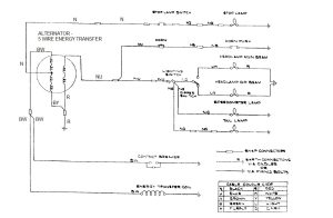
Testing a 5 wire ET Stator
Continuity Check with volt/ohm meter on 100 scale :
Between: Red and Brown 1 ohm
Between: Red and Blue 1 ohm
Between: Black/Yellow and Black/White (Black/Yellow Emgo units) 5.5 ohms

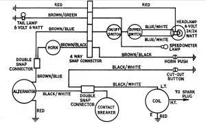
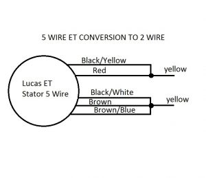
Convert a 5 wire ET to 12V DC
If you become frustrated with all this it is possible to convert your ET stator to DC by making the following connections: CONNECT: BLACK/YELLOW & RED LEADS TOGETHER. THIS FORMS ONE LEG
CONNECT: BROWN/BLUE, BROWN, & BLACK/WHITE. THIS FORMS THE SECOND LEG
Note: Some 4 wire ET stators can not be converted using this method. For example, due to internal wiring differences, the T20 Cub stator can not be wired as a 2 wire. Updating to a later DC system stator will be required.
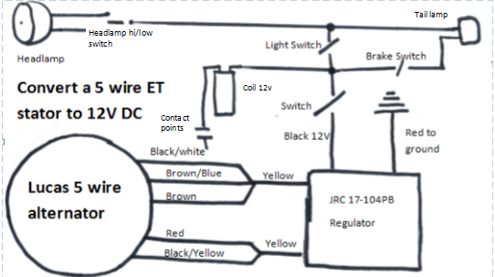
You can then connect a solid state regulator JRC 17-104PB. This unit contains a built in capacitor to enable running without a battery. Above is a simple wiring diagram for this conversion.
This conversion will require the following:
DC type coil(s) – Updating the bulbs to DC type (AC bulbs won’t last very long running on DC)
Caveats:
- Lucas ET rotors are now all over 60 years old. Left in the stator coil they will retain magnetism for a very long time but if your rotor was left standing without being in a stator or with out “keepers” it will have lost magnetism and output will be greatly reduced.
- Many 5 wire stators do not have the later epoxy encapsulation. Those with exposed coils used a stiff cardboard for insulation. This breaks down with time. It is recommended to replace all non-encapsulated stators with the later type.
- Alternator wire plastic insulation tends to become brittle with age and it is easy to have a crack in the wire covering allowing the alternator wires to short against each other. I have never had much luck trying long term repairs for this condition.
Other Options:
Converting to one of the Electrex World CDI units might be of interest. These replace the stator and use a self generating AC CDI ignition. Lights are optional on some kits.
Comments:
05/03/2022
Thanks to you I was able to diagnosis and repair a BSA Hornet that had ben disabled for what looks like decades. The final fix was to check the dowel position location for the rotor. At top dead center, the dowel was off approximately off 40 degrees. Without your information I would still be scratching my head! – Patric McCracken
1 thought on “Lucas ET Ignition Unraveled”
Andy
May 28, 2019 at 7:53 am
What a brilliant and informative site.
Comments are closed.